Pico-Pomona Clip Connection
To begin flashing the BIOS, you'll need to connect your Pico to the Pomona clip, which will then attach to the BIOS chip on your ThinkPad.
The Bios Chip
The BIOS chip in your ThinkPad models is an SOIC-8 type with 8 pins.
In these specific models, you’ll likely find two BIOS chips positioned next to each other. Both of these chips will need to be flashed. Don’t worry, though — the process is straightforward and will be explained in detail later in this guide.
IMPORTANT: Be sure to identify pin 1 (which is marked with a small dot) and then count the pins counterclockwise from there.

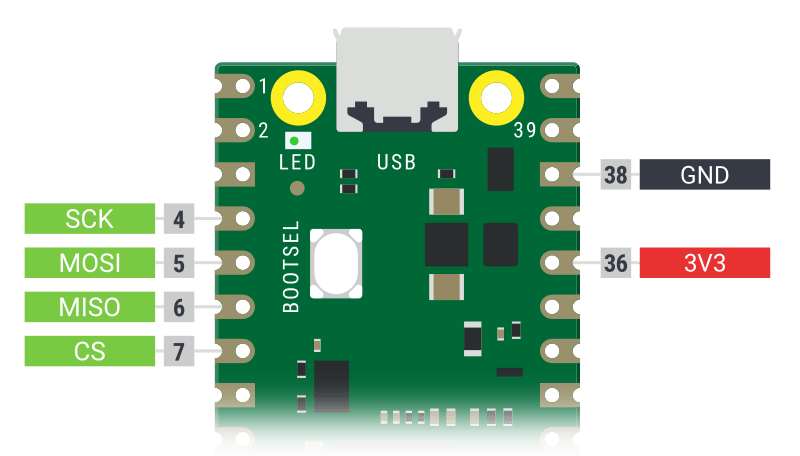
Here are the functions of each pin. You don't necessarily need to understand the purpose of each individual pin. Instead, you simply need to match the corresponding pin on your BIOS chip with the appropriate pin on your Raspberry Pico and connect them using Dupont cables.
- 1 CS
- 2 MISO
-
3 WP (this is NOT going to be used) - 4 GND
- 5 MOSI
- 6 CLK (this is actually SCK on your Raspberry Pico)
-
7 HOLD (this is NOT going to be used) - 8 VCC - 3V3 (this is actually 3V3 on your Raspberry Pico)
PIN Map on Raspberry Pico
The below diagram shows the corresponding pins on the Pico board where the Dupont cables should be connected

Models X230, T420, T430, T440p and T480s
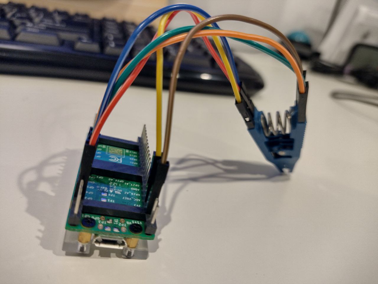
For these models, you can start wiring your Dupont cables directly from pin 1 of the BIOS chip — no extra tricks or workarounds are needed.
Once everything is connected properly, your setup should look like this:

Models T530 and W530
These ThinkPad models can be a bit tricky when it comes to BIOS flashing. They require a few extra tools and a small workaround to make the process reliable.
Both the T530 and W530 have two SOIC-8 flash chips connected to the same SPI bus. They share the data lines (MISO, MOSI, CLK), but each chip has its own Chip Select (CS#) line, which controls which chip is active at any time.
The Problem
When the Southbridge (the part of the motherboard that controls I/O) isn't powered, the CS# line of the inactive chip is left floating—meaning it's not pulled high or low, so it can randomly activate. This can lead to:
- Flash read/write errors
- Both chips responding at the same time
- Inconsistent BIOS dumps
You’ll notice this if you use a Pomona clip and read the BIOS multiple times: running something like sha1sum on the dumps will give different results each time.
This happens because there are no pull-up resistors on the CS# lines by default. So when the Southbridge is off, the chip you don’t want can still partly interfere with the bus.
The Solution
To stop the unused chip from interfering, you need to force its CS# pin HIGH (3.3V) so it stays inactive. This makes sure only the chip you want to access is talking on the SPI bus.
Requirements
Here’s a list of the extra tools required:
- Dupont cable (female-to-female)
- Test Hook Clip Grabber (link)
- AMS1117-3.3V Power Supply Module (link)
- Universal Adapter with Selectable Output Voltage (link)
Connection Steps
Here’s how to connect everything:
- Connect the dupont cable to the test hook clip.
- Use the hook clip to grab the CS# pin of the flash chip that’s not being used (the one you’re not flashing).
- Connect the other end of the dupont cable to the VCC (3.3V output) on the AMS1117 power module.
- Connect GND from your Raspberry Pi Pico to the GND of the AMS1117.
- Set the Universal Adapter to 5V output and plug it into the AMS1117 module. The reason for this is that the AMS1117 is a voltage regulator. It needs a higher input of 5V to convert it into the lower 3.3V output that your circuit requires.
- Clip the Pomona to the chip you want to flash and connect it to your flasher (e.g., Raspberry Pi Pico).
- Power on the Universal Adapter. You should see a red LED light up on the AMS1117 module.
- Power on the AMS1117 module. You should see a red LED light up on the module.
Now the inactive chip is fully disabled, and you’re ready to flash the BIOS reliably.
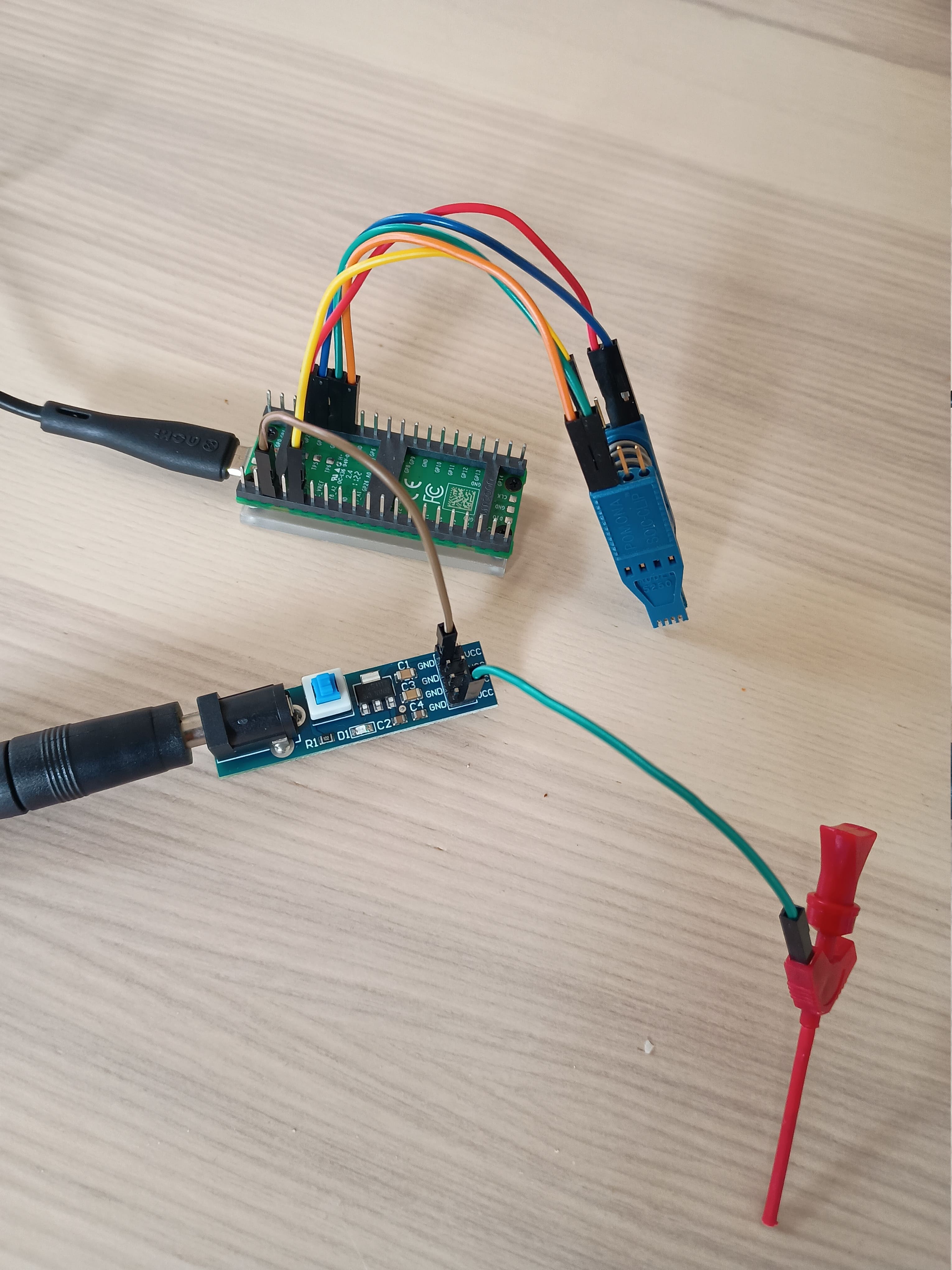
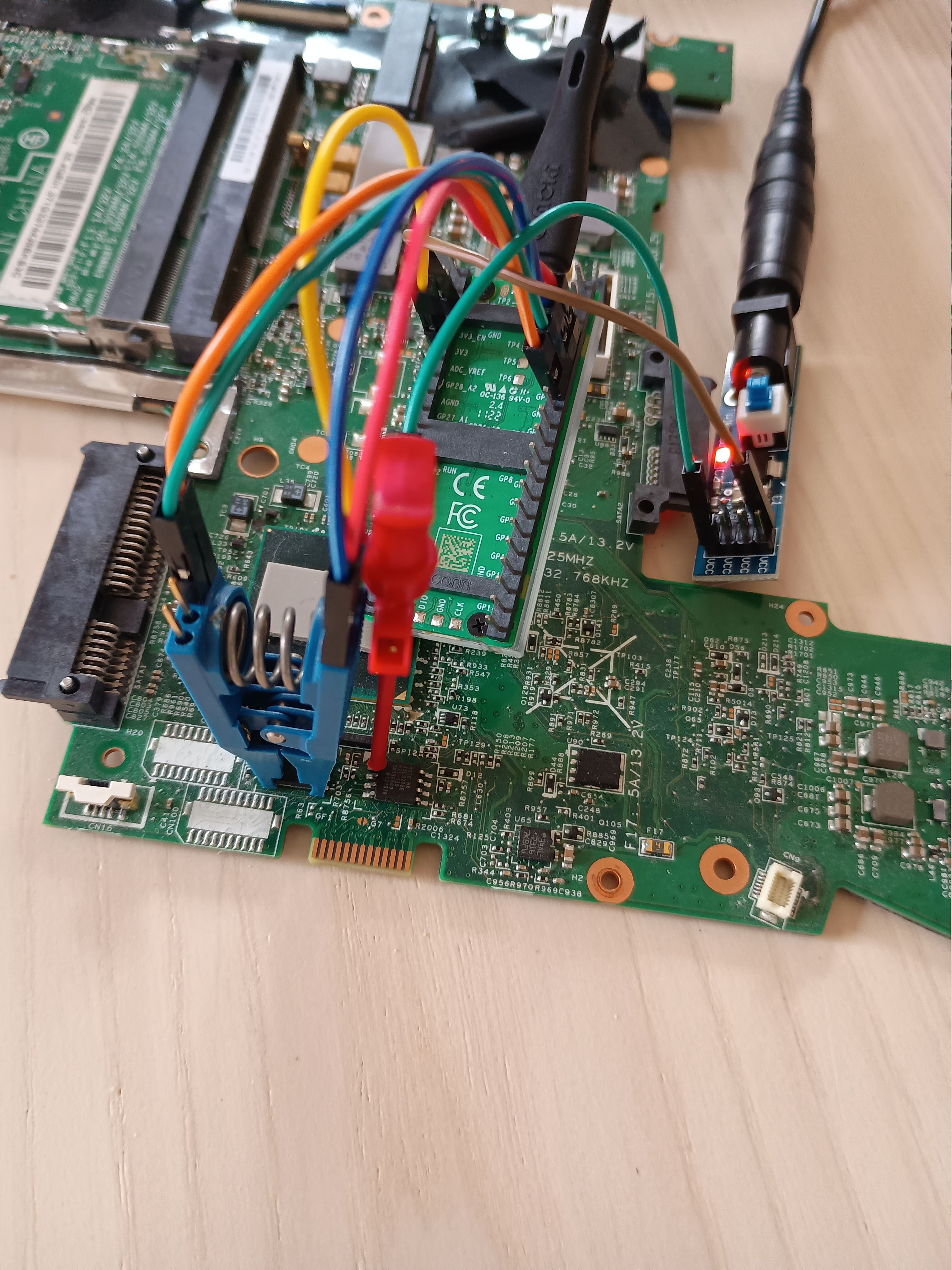
Setup Photos
Here’s what the setup looks like:


Conclusion
Now you're ready to clip onto the chip and start flashing the BIOS — with stable and consistent reads and writes!